GRiDCase 1520 DC-DC Converter Repair
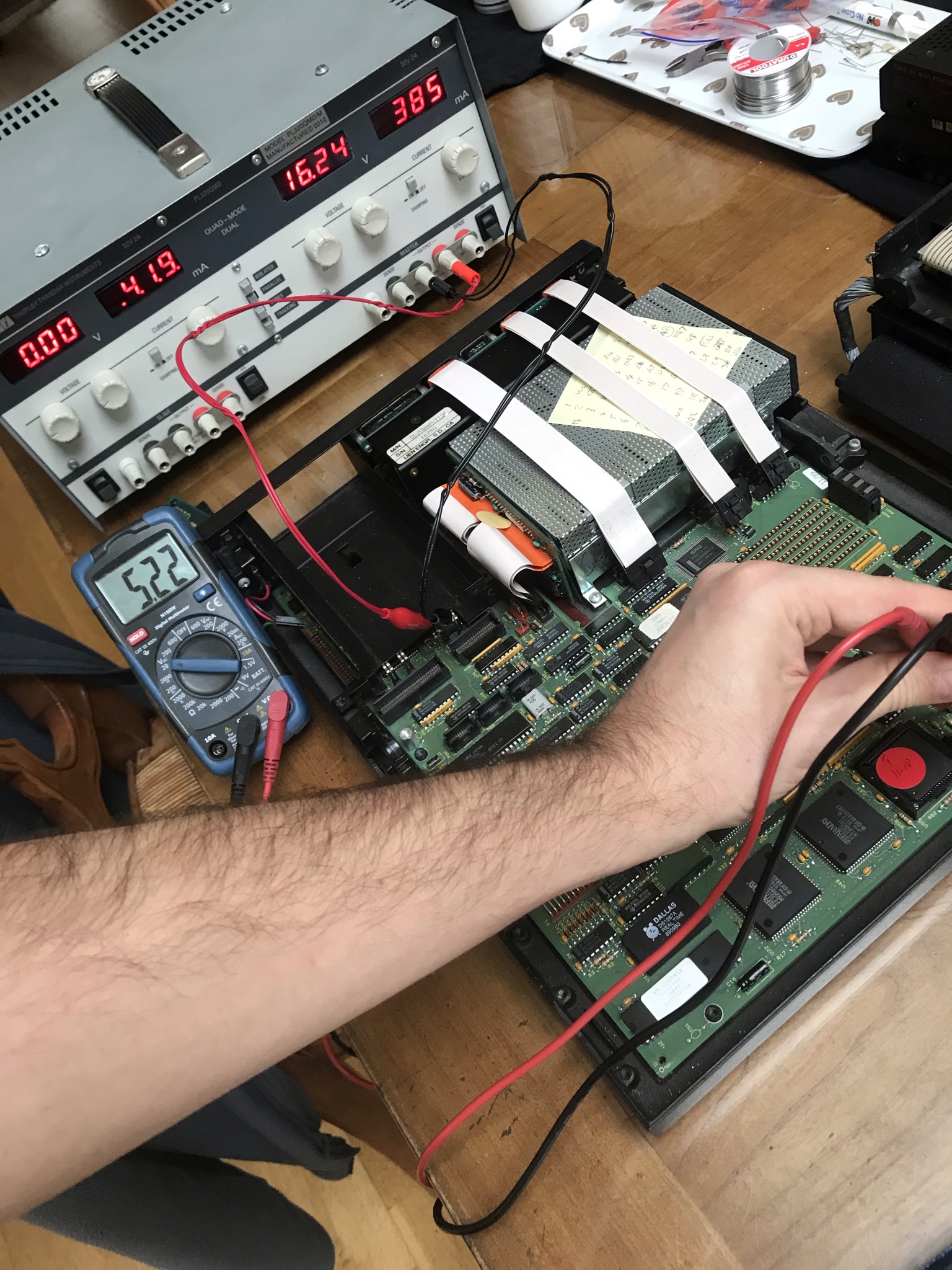
While diagnosing a RAM failure in my more sickly GRiDCase 1520 I noticed an unpleasant odour coming from the rear of the machine. Pretty soon it started behaving erraticly, rebooting at random. It's capacitors again — this time in the DC-DC converter module. Time to break out the soldering iron!
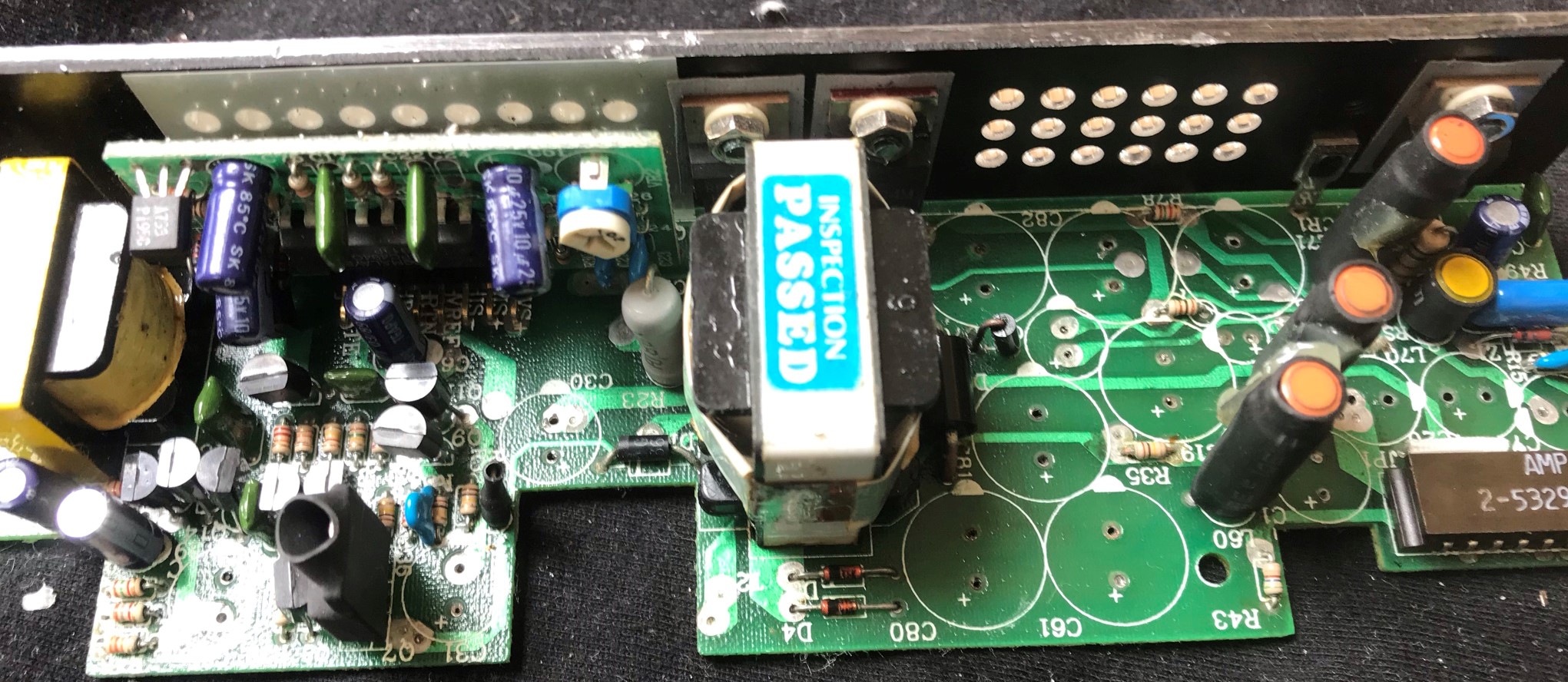
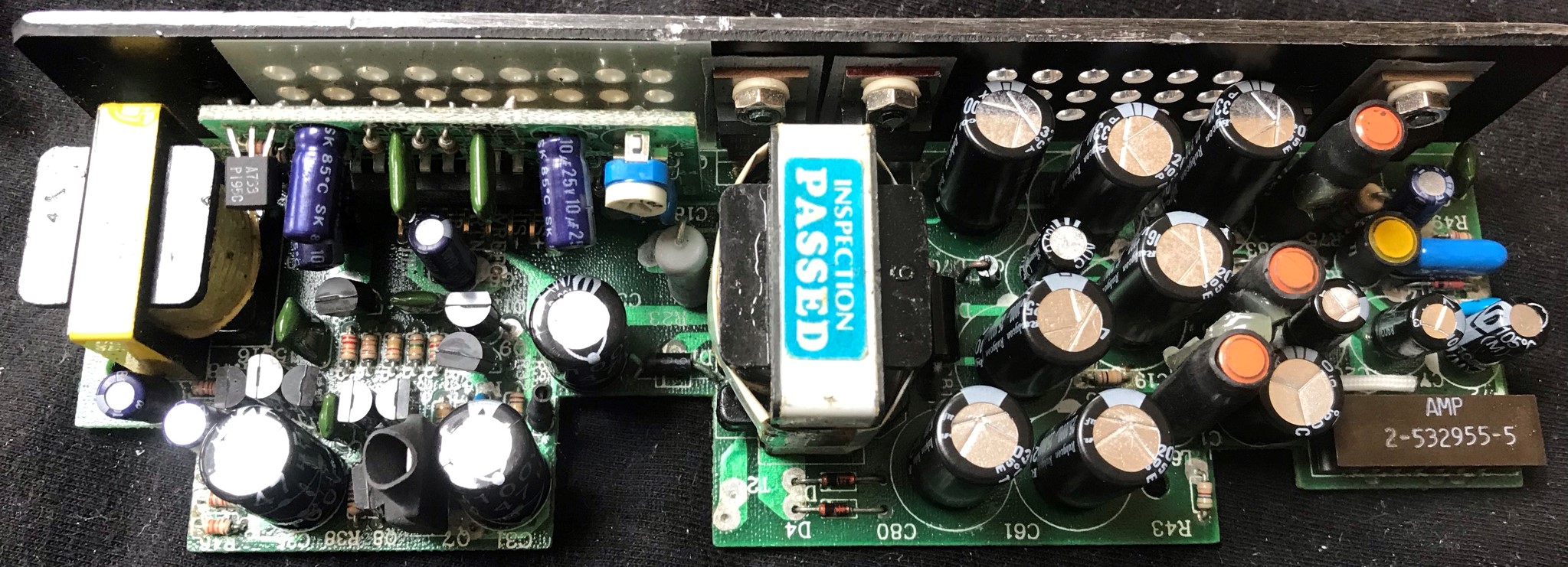
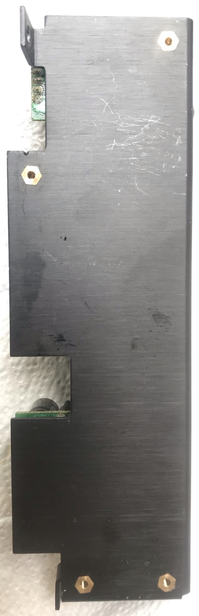
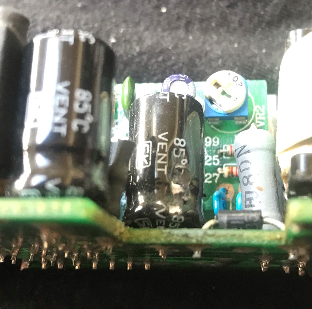
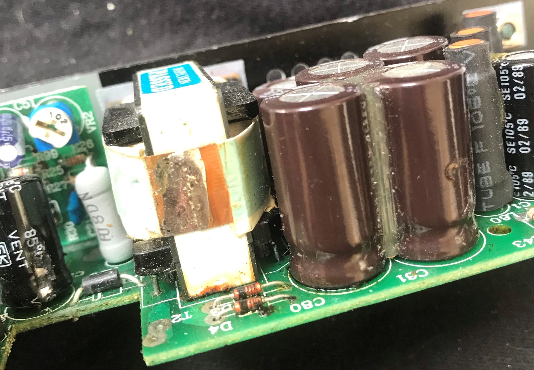
Extracting the DC-DC converter requires opening up the computer. It was immediately obvious that at least one large capacitor had leaked: underneath the DC-DC converter a brownish liquid was pooling. It also coated the lower half of the converter PCB :-(
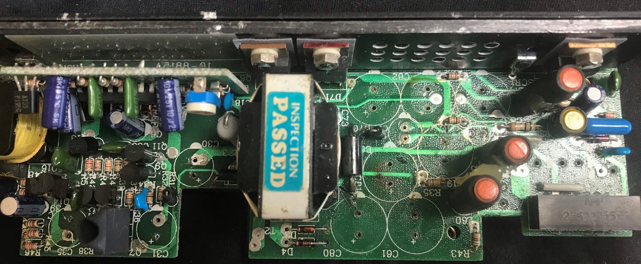
DC-DC Converter Overview
The DC-DC converter takes the DC input to the system (16.24V from battery/PSU bay or 9-20V from external barrel connector). It converts this to the various voltages required for the rest of the system.
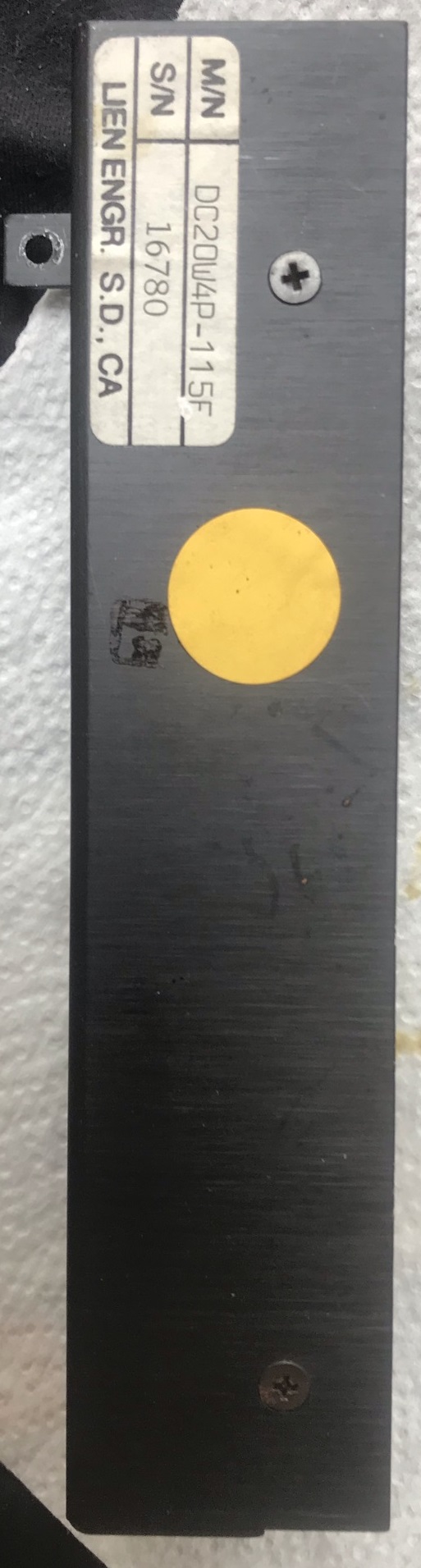
There are multiple models for the GRiDCase 1500-series DC-DC Converter:
- LCD-115, GRiD part number 104144-00. Used with the two LCD display options. Provides −15, +5, and +12 DC outputs plus switchable 100VAC.
- PLASMA-116, GRiD part number 104145-00. Used with the two plasma display options. Provides −15, +5, +12, and +33V DC outputs.
The machine I'm repairing here had an LCD display.
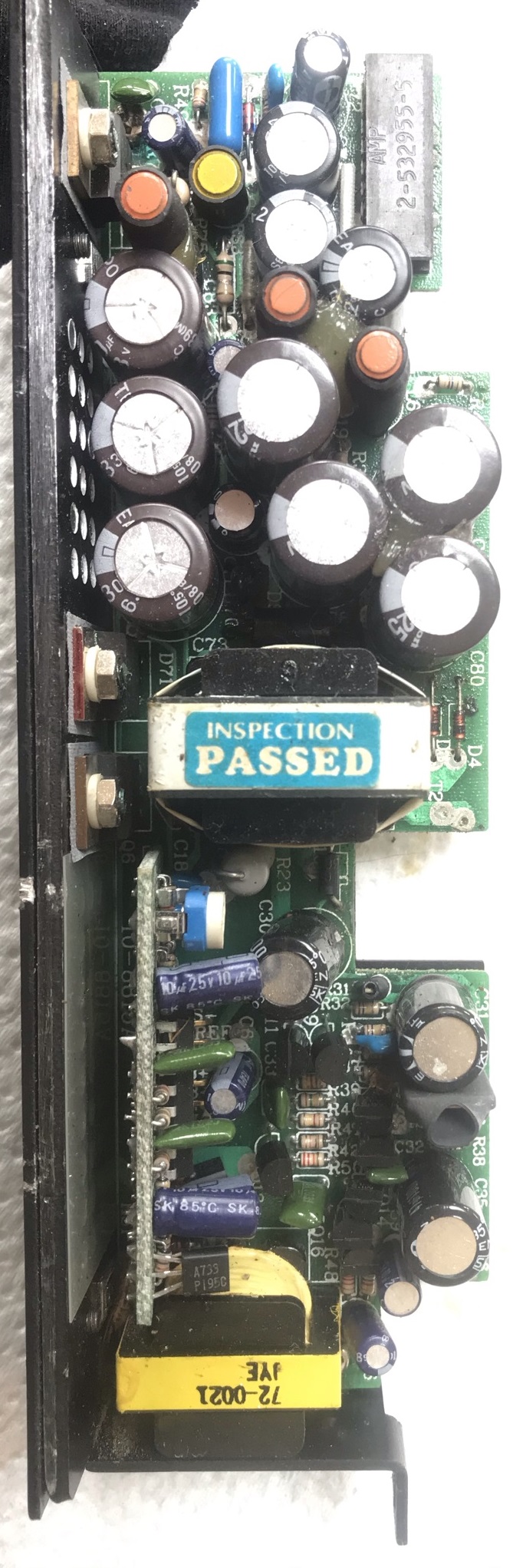
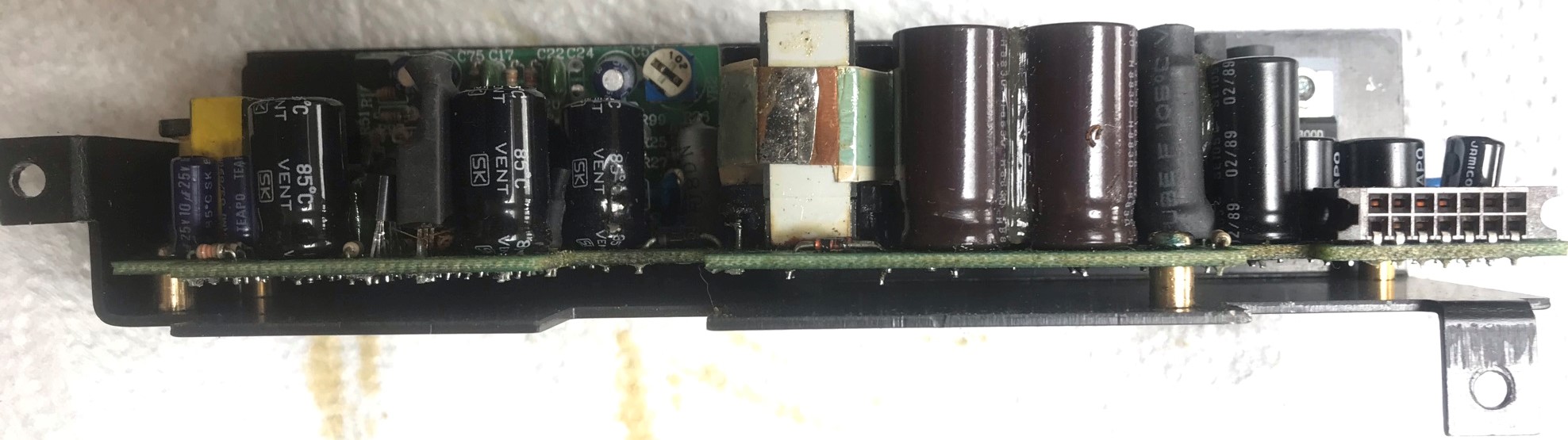
Removing the Capacitors
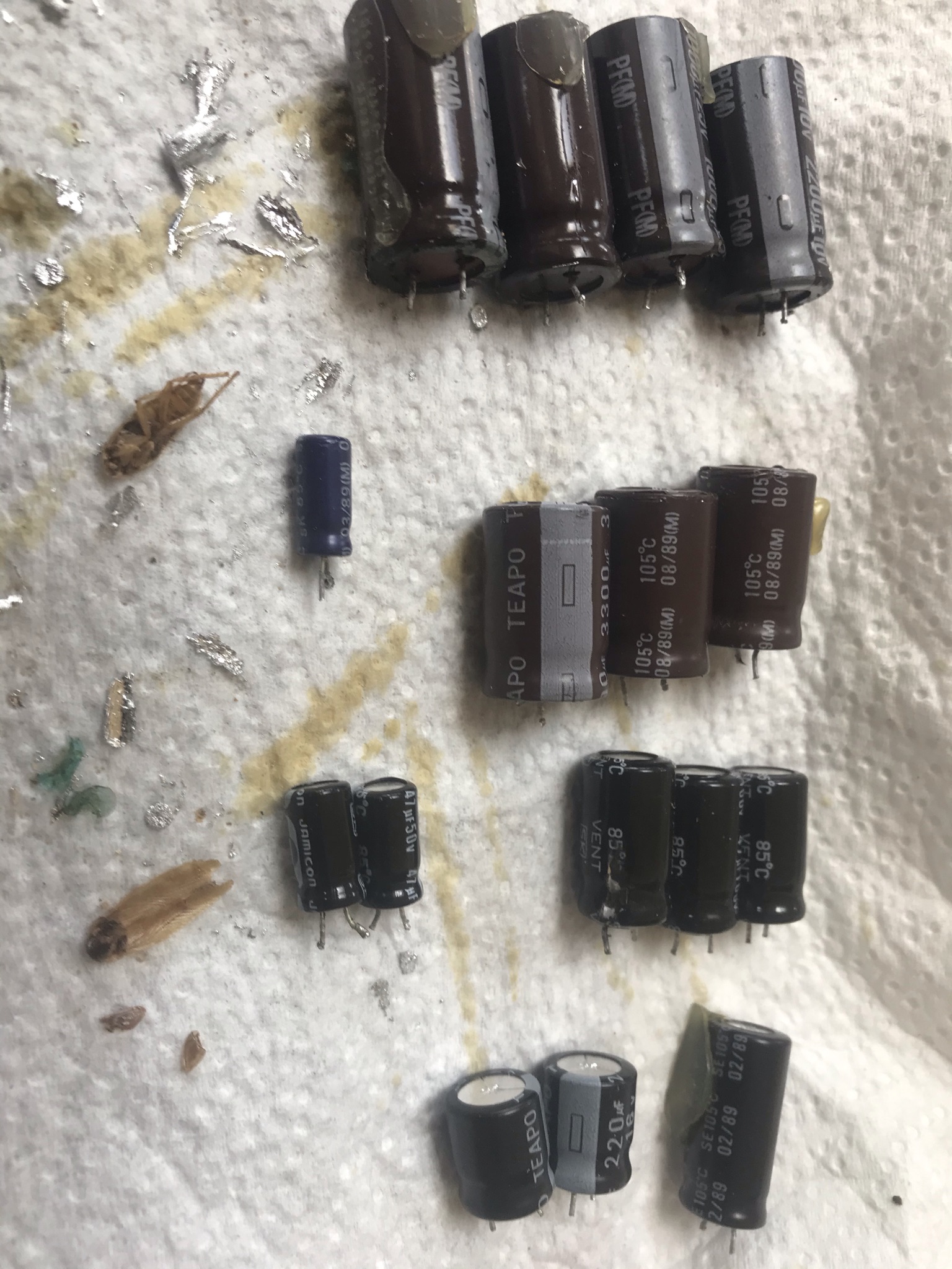
The capacitors I removed and their values were:
| Designator | Capacitance µF | Voltage V | Max Temp °C | Height mm | Diameter mm | Lead Spacing mm |
|---|---|---|---|---|---|---|
| C1 | 470 | 25 | 105 | 21 | 10 | 5 |
| C19 | 2200 | 10 | 105 | 25 | 13 | 6 |
| C20 | 220 | 16 | 105 | 12 | 5 | 5 |
| C30 | 47 | 100 | 85 | 17 | 10 | 6 |
| C31 | 47 | 100 | 85 | 17 | 10 | 6 |
| C35 | 47 | 100 | 85 | 17 | 10 | 6 |
| C61 | 1000 | 25 | 105 | 25 | 13 | 6 |
| C71 | 47 | 50 | 85 | 12 | 6 | 3 |
| C72 | 47 | 50 | 85 | 12 | 6 | 3 |
| C73 | 3300 | 6.3 | 105 | 20 | 10 | 5 |
| C74 | 470 | 6.3 | 105 | 12 | 10 | 5 |
| C76 | 10 | 10 | 85 | 11 | 13 | 2 |
| C80 | 1000 | 25 | 105 | 25 | 13 | 6 |
| C81 | 1000 | 25 | 105 | 25 | 13 | 6 |
| C82 | 3300 | 6.3 | 105 | 20 | 13 | 5 |
| C83 | 3300 | 6.3 | 105 | 20 | 13 | 5 |
I managed to source replacements that met the capacitance; met or slightly exceeded the voltage and temperature rating; and were physically the same size or smaller.
Fitting Replacements