Repairing a Gridcase 1520 Power Supply
A few years ago the power supply for my Gridcase 1520 portable computer died. It emitted a cloud of bad-smelling smoke and wouldn't turn on again. I placed it to one side and forgot about it for a few years. Now it's time to get it working again!
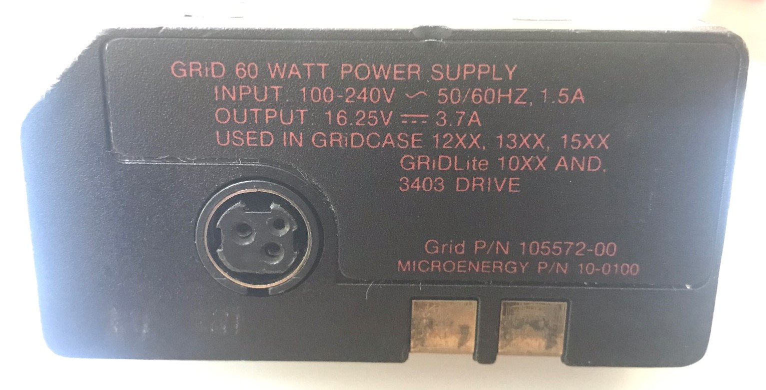
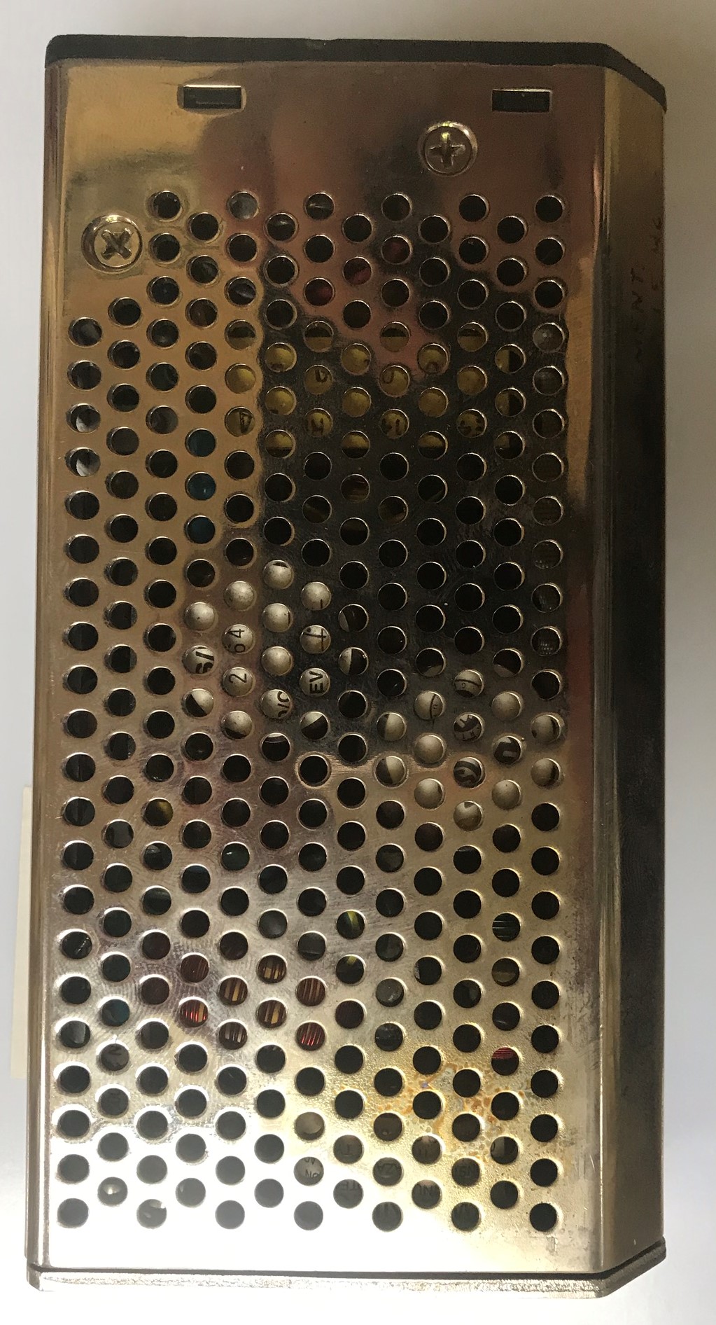
The Grid 15xx-series of portable computers use a removable power supply. It's shaped a bit like like a brick with one edge rounded off. Once the power supply is removed it can be replaced with a battery pack and the power supply used as an external charger. I have a couple of battery packs but they are long since dead and will not hold a charge. Maybe I'll open one up one day and see if they're fixable…
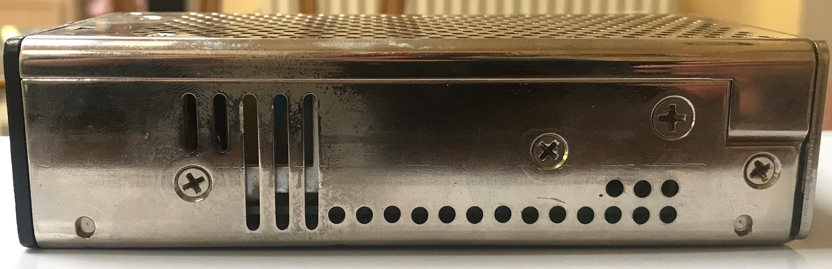
Opening up the power supply
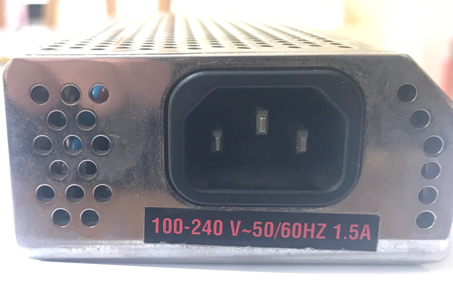
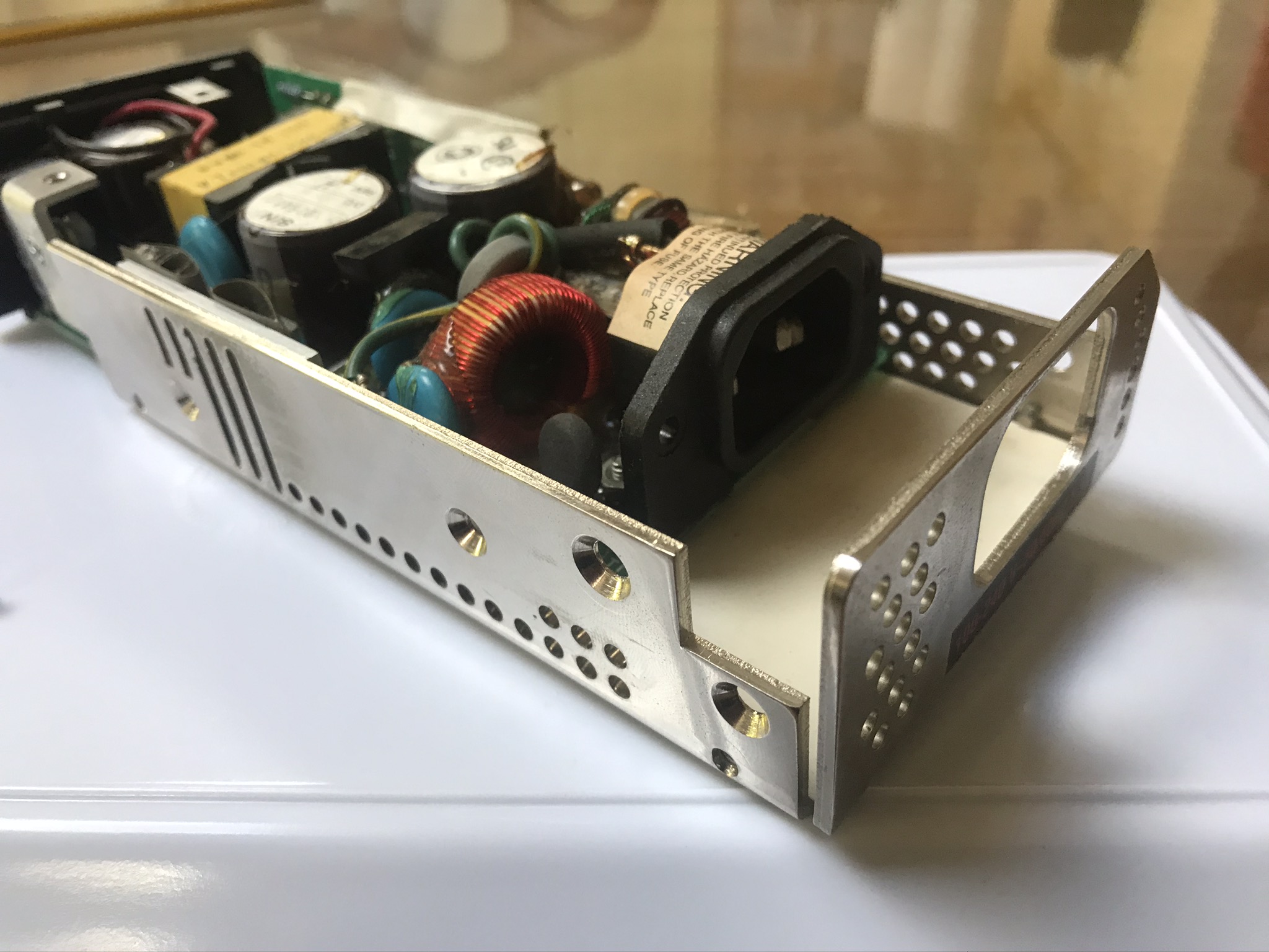
Directions in this text assume that the power supply is oriented as if you were facing the rear of the computer about to insert it; i.e. with the IEC (kettle lead) socket facing you as shown in the image above. Obviously the power supply deals with mains voltage (240V here) so it should be unplugged while you are working on it.
Replacing the capacitors
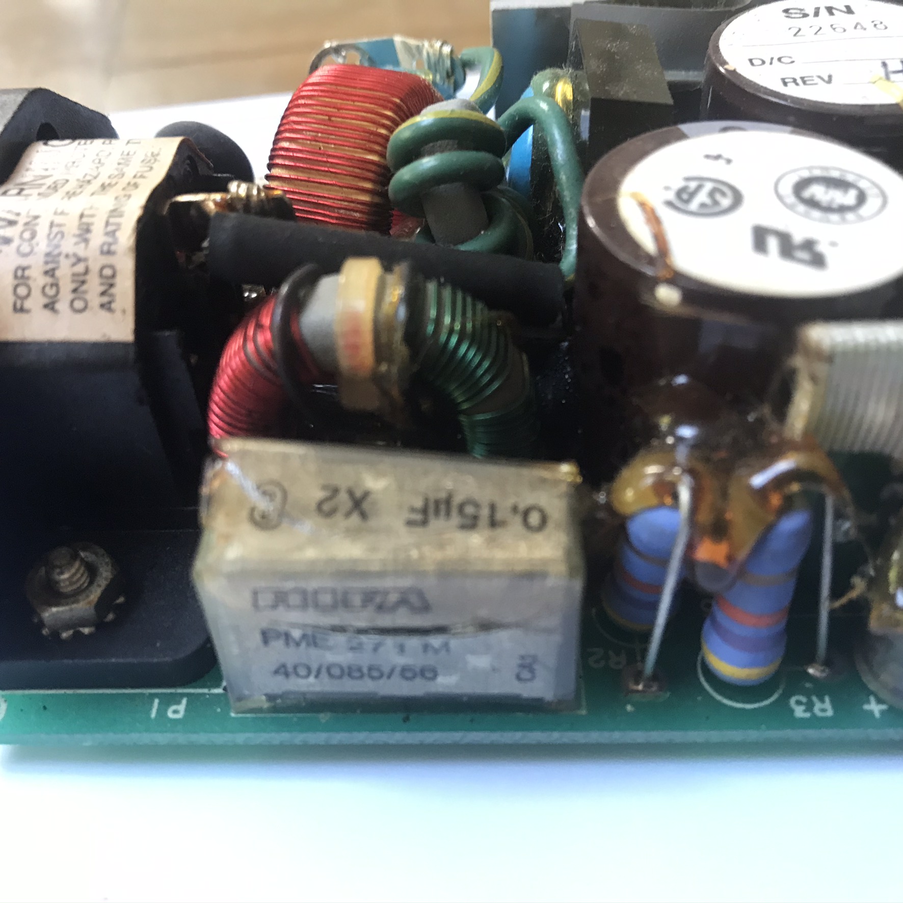
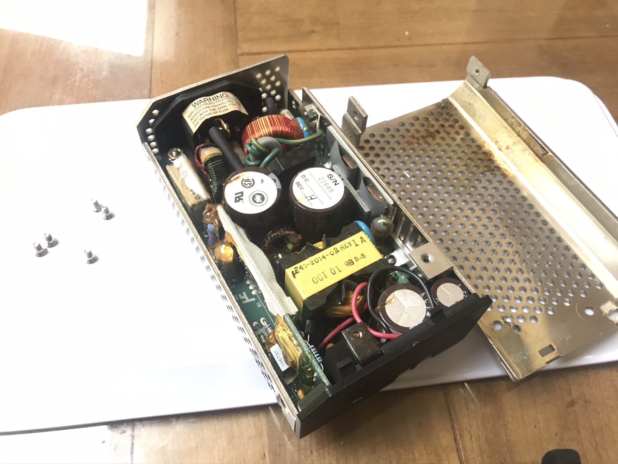
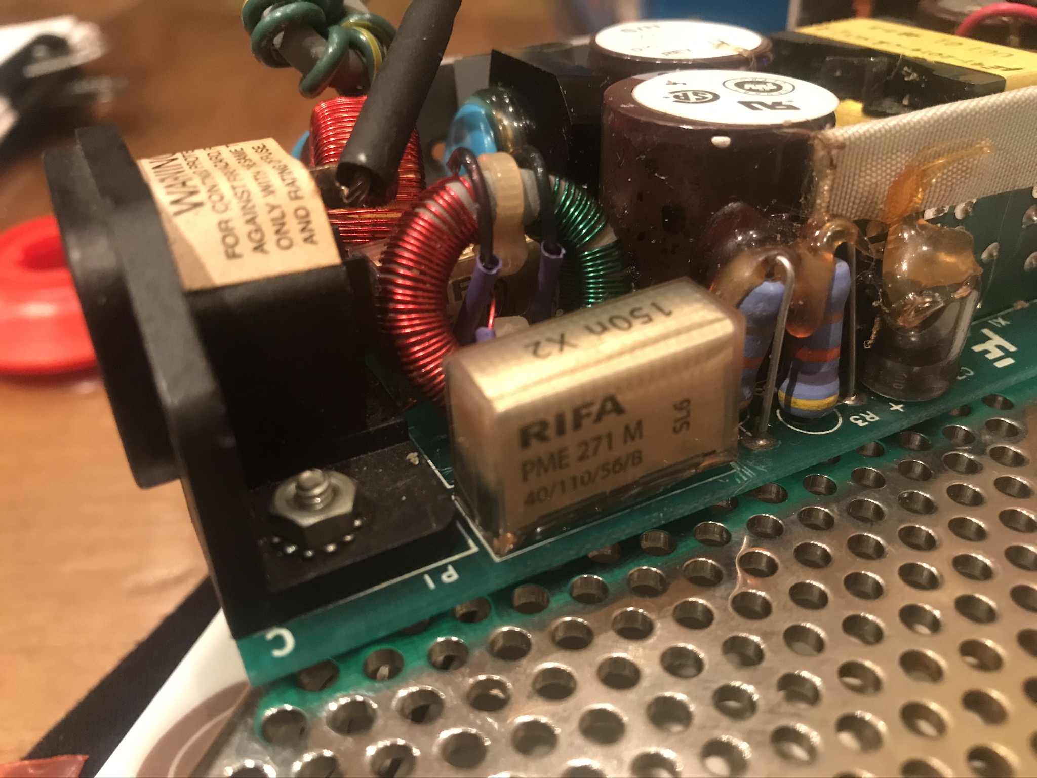
With the cover removed it was very obvious what the problem was: two Rifa-style capacitors had expelled all their magic smoke.
These are metalized film capacitors used as filters across the mains power supply, so they've had the full 240V ripping them apart.
Because these are in a power supply across the mains input they're also X2 safety capacitors designed to fail safely.
Replacement parts must have an equivalent rating in order to be safe.
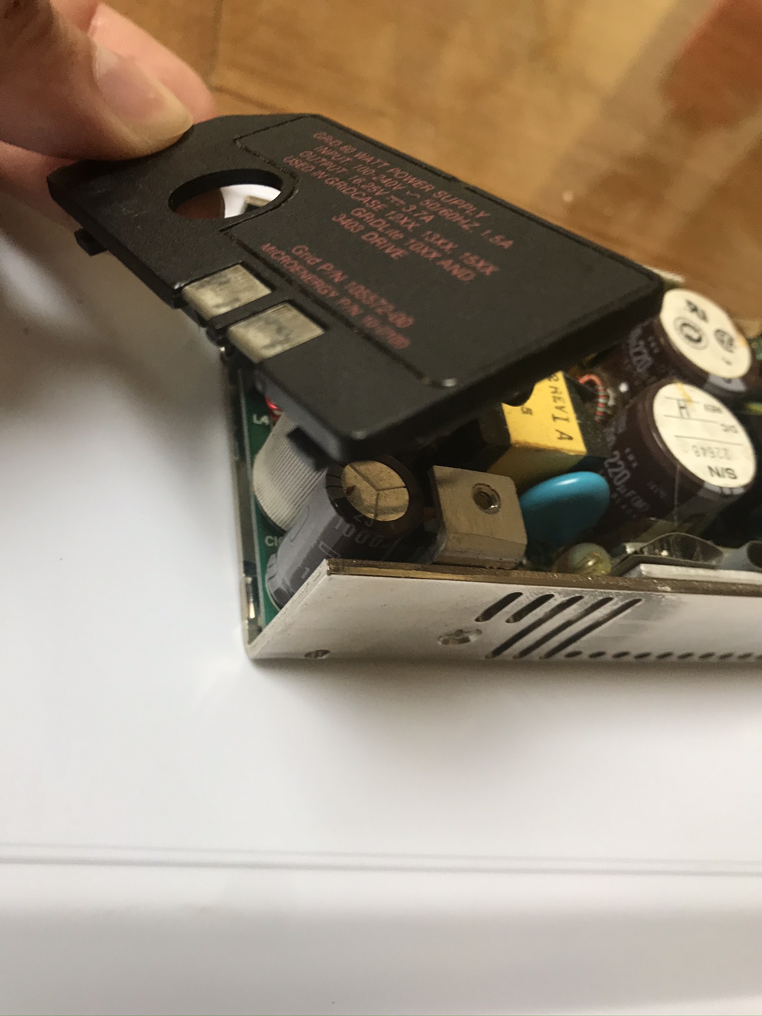
Fortunately enough of the outer capacitor was intact that I could read the part number: PME 271 M 40/100/56/B X2-type at 0.15µF 275V.
A bit of searching found a datasheet with a compatible equivalent from Kemet: PME271M615KR30 from £1.44 each.
Not cheap but worth it to get a near-identical replacement.
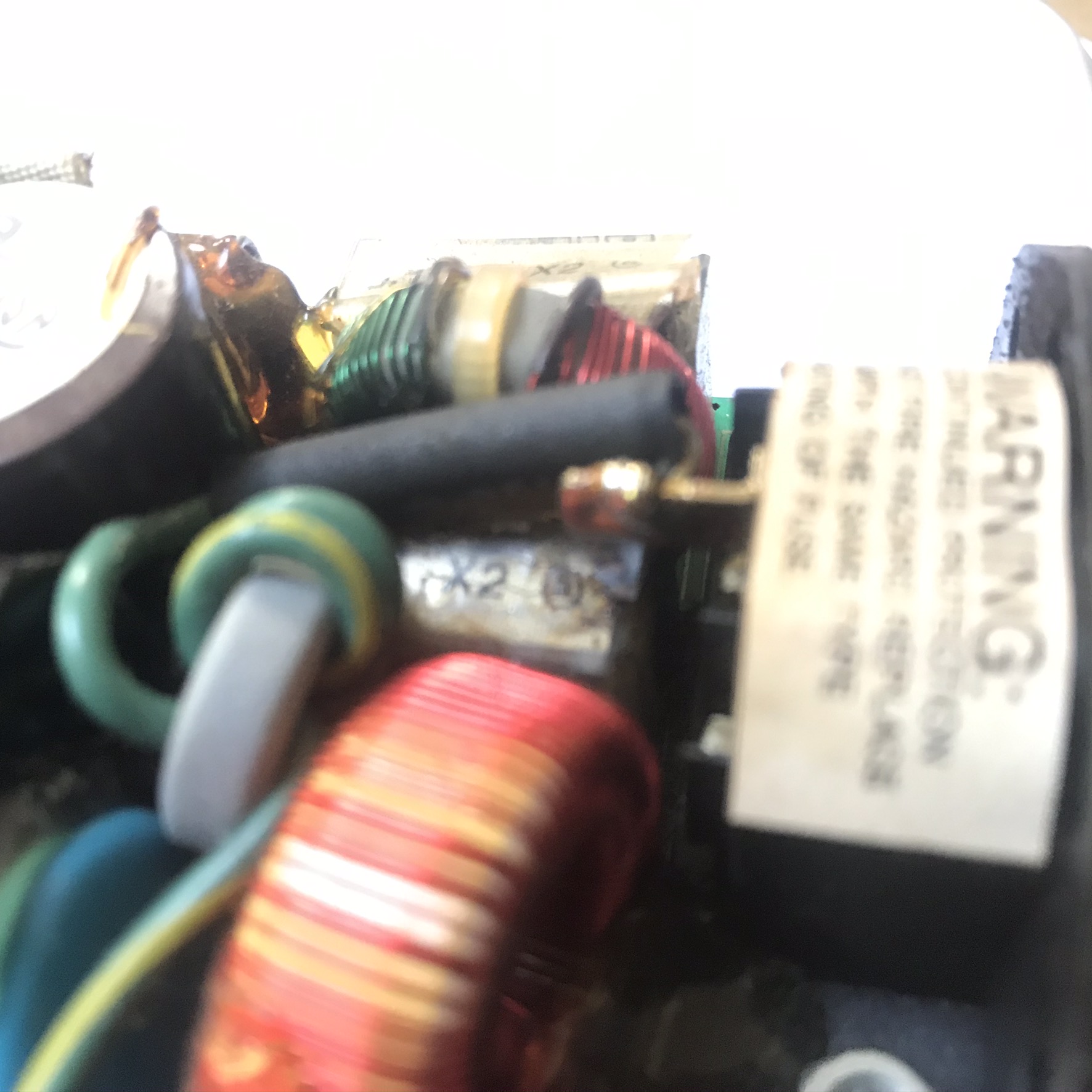
Unfortunately for me not only is it very cramped in there with the capacitors crammed up against a couple of inductors but Grid have also covered the contents of the power supply with copious amounts of resin. This is intended to reduce noise by preventing components (particularly inductors) from vibrating and can also help with thermal transfer.
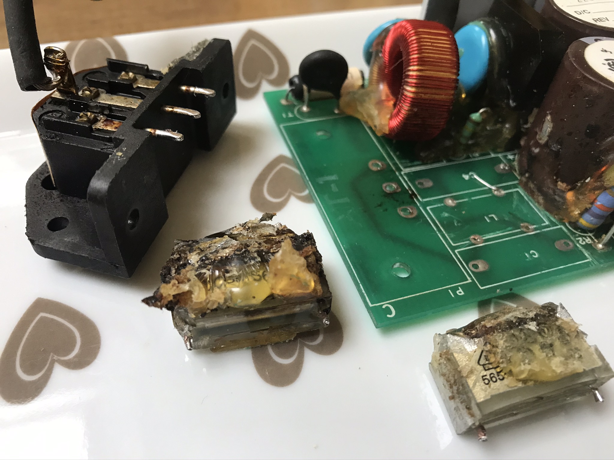
I tried scraping and cutting the resin but with very little effect -- it's not soft like putty but hard like plastic. Time for plan B: I bought some acetone hoping it would dissolve the resin. It didn't, but it did cause the resin to soften and become incredibly sticky, almost like warm toffee.
I didn't think I had space to work on the capacitors with the inductor sandwiched between them, so I used a solder sucker on the reverse of the PCB to free all three components leaving just the resin holding them down. After removing the IEC socket to get a better angle of attack, I used the acetone along with a stanley knife to remove the capacitors and the inductor.
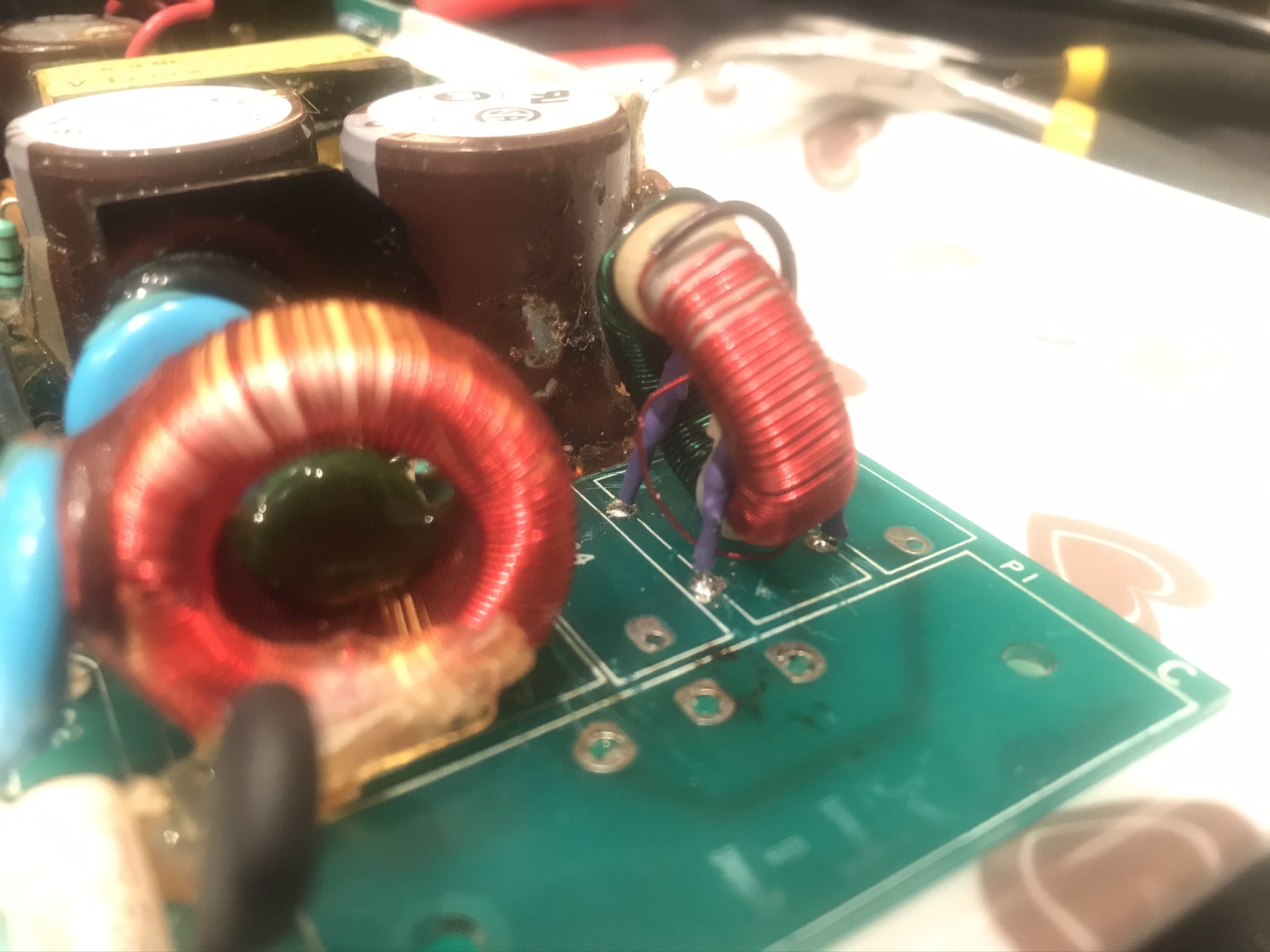
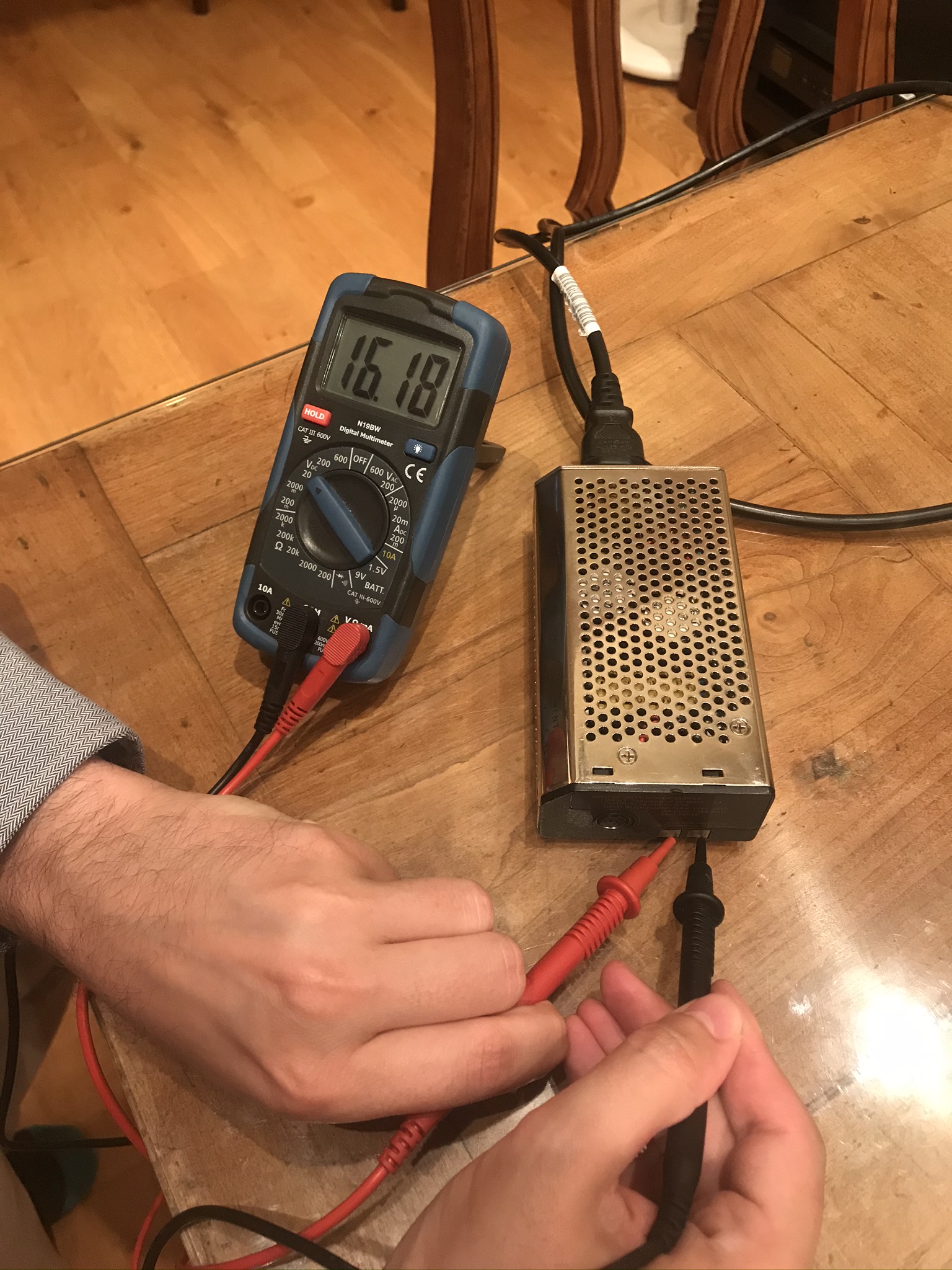
A quick test went OK with nothing exploding. Let's see if it works!
Final result
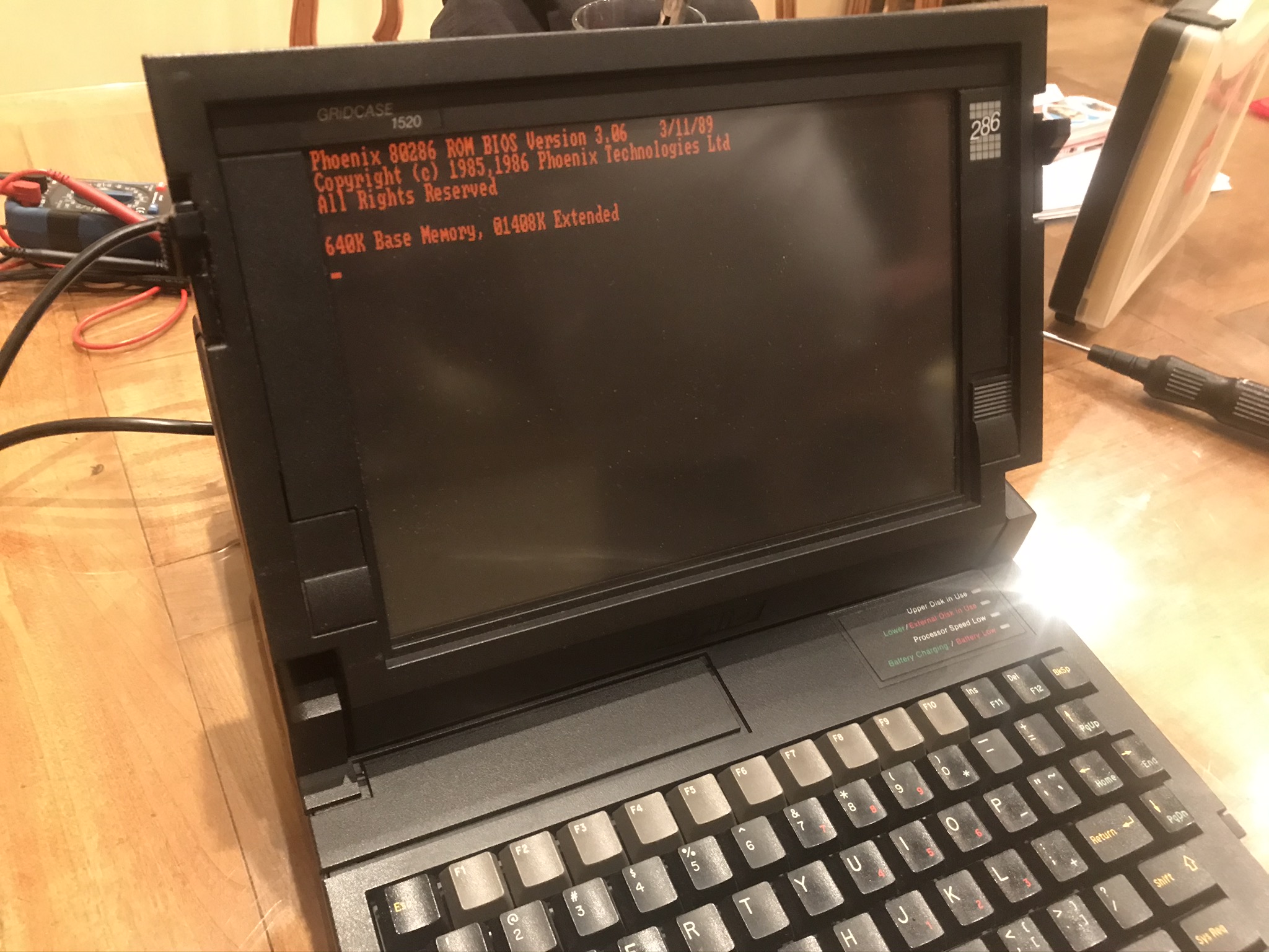
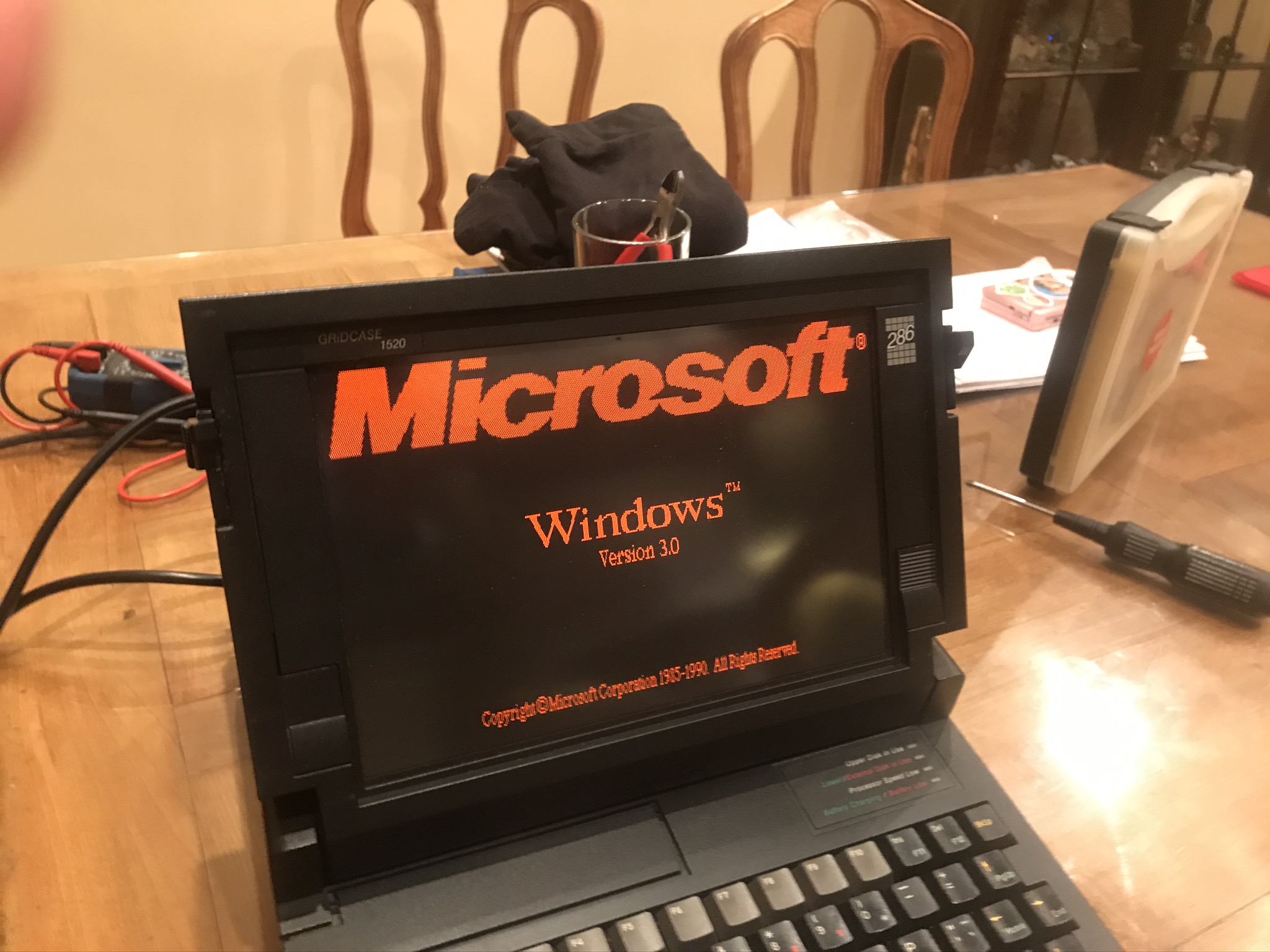
I'm going to call that a success!